Building & Mechanical Online-Note

Month: January 2024 Page 1 of 2

What factors determine the selection of a PV Series Pump for a specific application?

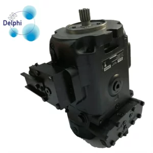
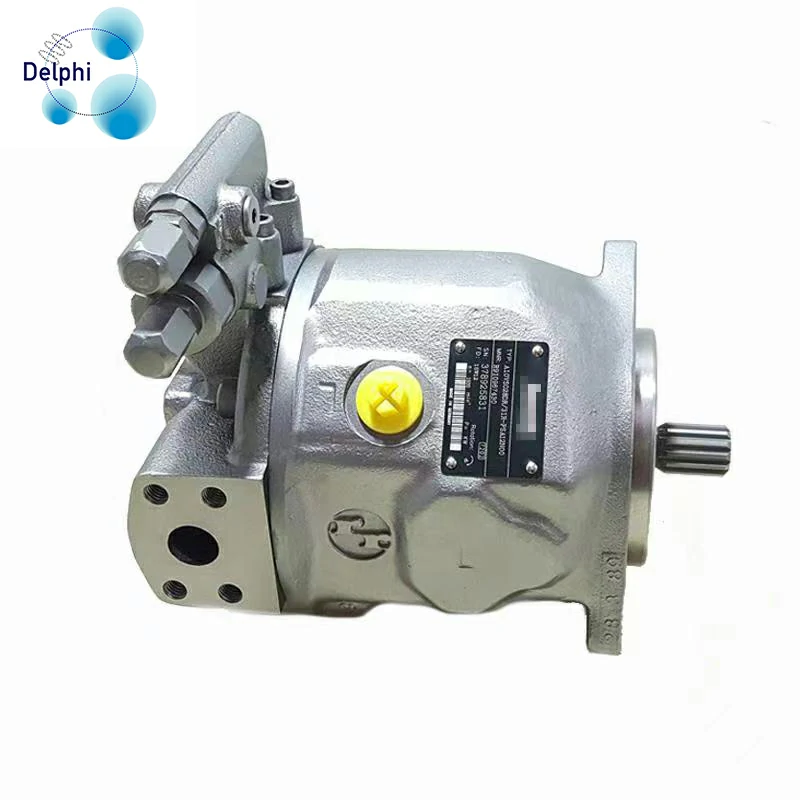
The selection of a PV Series Pump for a specific application involves considering various factors to ensure optimal performance and efficiency. The PV Series Pumps are variable displacement, axial piston pumps commonly used in hydraulic systems.

Here are key factors that determine the selection of a PV Series Pump for a particular application:

  1. Flow Rate Requirements:
    • The required flow rate of hydraulic fluid is a critical factor. It depends on the application’s demands, such as the speed and force needed for hydraulic actuators.
  2. Pressure Requirements:
    • Consider the maximum operating pressure required for the application. China PV Series Pump manufacturer Different PV Series Pumps may have different pressure ratings, and selecting a pump with an adequate pressure rating ensures it can handle the system’s demands.
  3. Displacement Range:
    • PV Series Pumps are variable displacement pumps, and the displacement setting determines the flow rate. The range of available displacements should be suitable for the application’s specific needs.
  4. Speed Range:
    • Consider the speed range of the hydraulic system. The pump should operate efficiently within the specified speed range to meet the application’s performance requirements.
  5. Control Options:
    • PV Series Pumps often come with various control options, such as pressure compensators, load sensing, or electric proportional control. The choice depends on the system’s requirements for pressure control, energy efficiency, and response time.
  6. Mounting Configuration:
    • The pump’s mounting configuration should match the space available and the installation requirements of the application. PV Series Pumps are available in various configurations, including flange, foot, and through-drive options.
  7. Fluid Compatibility:
    • Ensure that the pump is compatible with the hydraulic fluid used in the system. Consider factors such as fluid viscosity, temperature range, and contamination sensitivity.
  8. Noise Levels:
    • Some applications have strict noise requirements. Selecting a PV Series Pump with features like advanced noise reduction can be crucial in noise-sensitive environments.
  9. Efficiency and Energy Consumption:
    • Consider the overall efficiency of the pump, as it can impact the energy consumption of the hydraulic system. High-efficiency pumps contribute to energy savings.
  10. Environmental Conditions:
    • Assess the environmental conditions in which the pump will operate. This includes temperature extremes, exposure to contaminants, and potential corrosive environments.
  11. Reliability and Maintenance:
    • Evaluate the reliability of the pump and the ease of maintenance. Pumps with robust designs and easy serviceability can reduce downtime and maintenance costs.
  12. Budget Constraints:
    • Consider budgetary constraints and select a pump that provides the necessary performance within the specified cost range.
  13. Manufacturer Support and Documentation:
    • Choose a reputable manufacturer that provides comprehensive technical documentation, support, and a warranty. Manufacturer support is essential for troubleshooting and maintenance.
  14. Future Expansion:
    • Consider the potential for system expansion or modifications. Choosing a versatile pump that can adapt to changing requirements helps future-proof the hydraulic system.

By carefully evaluating these factors in the context of the specific application requirements, engineers and system designers can make informed decisions when selecting a PV Series Pump for optimal performance and reliability.


How is the F11 Series Motor’s performance affected by changes in system load?

The performance of the F11 Series Motor, like other hydraulic motors, can be influenced by changes in the system load. Hydraulic motors, including the F11 Series, are designed to convert hydraulic energy into mechanical power to drive various applications. Here are the ways in which changes in system load can affect the performance of the F11 Series Motor:

  1. Speed and Torque Relationship:
    • The F11 Series Motor operates on the principle that the motor speed and torque are inversely proportional. As the load on the motor increases, the output speed tends to decrease, while the output torque increases. Conversely, a lighter load results in higher speed and lower torque.
  2. Pressure Drop Across the Motor:
    • An increase in system load often leads to higher pressure drops across the motor. This can impact the overall efficiency and performance of the motor. It’s important to ensure that the hydraulic system is designed to provide adequate pressure for the given load.
  3. Efficiency and Heat Generation:
    • Changes in system load can affect the overall efficiency of the F11 Series Motor. Operating the motor under heavy loads for extended periods may lead to increased heat generation, potentially impacting the efficiency and requiring proper cooling measures.
  4. Control Response:
    • For systems using variable displacement hydraulic motors like the F11 Series, changes in load can influence the control response. Load variations may necessitate adjustments to the motor displacement to maintain the desired speed and torque levels.
  5. Power Consumption:
    • The power consumption of the F11 Series Motor is directly related to the load on the motor. Higher loads generally result in increased power consumption. It’s important to size the motor appropriately for the expected load range to ensure optimal performance.
  6. System Stability:
    • Sudden changes in system load can impact stability. Adequate control mechanisms, such as proportional or servo control systems, China F11 Series Motor manufacturer  may be required to maintain stability and responsiveness, especially in applications with rapidly changing loads.
  7. Cavitation Risk:
    • Heavy loads may increase the risk of cavitation, particularly if the hydraulic system is not properly designed or if the fluid supply is insufficient. Cavitation can lead to damage and reduced performance.
  8. System Response Time:
    • The response time of the hydraulic system to changes in load is crucial, especially in applications requiring quick and precise adjustments. Proper tuning of the control system and the use of appropriate feedback mechanisms contribute to responsive system performance.
  9. Mechanical Wear:
    • Frequent and significant changes in load can contribute to mechanical wear on the motor components. Regular maintenance and monitoring are essential to address any wear issues and ensure the motor’s longevity.
  10. Overall System Design:
    • The impact of changes in system load on the F11 Series Motor is closely tied to the overall design of the hydraulic system. A well-designed system, including appropriate control mechanisms, sizing, and fluid supply, can help optimize the motor’s performance under varying loads.

It’s crucial to consider the expected operating conditions, load variations, and control requirements when selecting and implementing the F11 Series Motor in a hydraulic system. Proper sizing, control strategies, and system design contribute to reliable and efficient motor performance across a range of loads.

How does the pump speed impact the flow rate in a A10VSO31 Series Pump?

The flow rate of a hydraulic pump, including the A10VSO31 Series Pump, is directly influenced by the pump speed. The relationship between pump speed and flow rate is described by the pump’s displacement, which is a key parameter in hydraulic systems.

The general relationship can be expressed by the following formula:

�=��

Where:

  • is the flow rate (volume of fluid per unit of time),
  • is the pump displacement per revolution or stroke (volume of fluid displaced by the pump in one complete revolution or stroke),
  • is the pump speed (number of revolutions or strokes per unit of time).

In the case of the A10VSO31 Series Pump:

  • Displacement (): The displacement value is a specific parameter associated with the pump and is typically provided by the pump manufacturer. It represents the volume of fluid displaced by the pump in one revolution or stroke.
  • Speed (): The speed is the rotational speed of the pump, measured in revolutions per minute (RPM) or strokes per minute, A10VSO31 Series Pump manufacturer  depending on the pump type.
  • Flow Rate (): The flow rate is the amount of hydraulic fluid delivered by the pump per unit of time, expressed in cubic units per unit of time (e.g., cubic inches per minute or liters per minute).

Impact of Pump Speed on Flow Rate:

  1. Increasing Speed:
    • When the pump speed () increases, the flow rate () also increases proportionally. This is because more revolutions or strokes per minute result in a higher volume of fluid being displaced by the pump.
  2. Decreasing Speed:
    • Conversely, when the pump speed decreases, the flow rate decreases accordingly. The pump is displacing a smaller volume of fluid per unit of time.

Considerations:

  • The relationship described assumes that the pump operates under ideal conditions, and other factors, such as pressure, temperature, and efficiency, remain constant.
  • Actual flow rates may be affected by the system’s pressure requirements, pump efficiency, and the presence of pressure compensators or other control mechanisms.
  • Pump speed adjustments are often used to control the output of hydraulic systems and match the flow rate to the specific requirements of the application.
  • It’s important to consult the pump’s technical documentation or contact the manufacturer for specific displacement values and speed limitations associated with the A10VSO31 Series Pump.

In summary, the flow rate in a hydraulic system with an A10VSO31 Series Pump is directly proportional to the pump speed, given a constant displacement value. Adjusting the pump speed allows for control over the flow rate to meet the demands of the hydraulic system.

4 Inch Silicone Hose: The Ultimate Guide

When it comes to versatility and durability, 4 inch silicone hose stands out from the rest. This type of hose is made from high-quality silicone material that provides excellent flexibility and resistance to heat, chemicals, and abrasion. In this article, we will explore the various applications and benefits of 4 inch silicone hose, as well as provide tips on how to choose the right one for your needs.

Applications and Benefits:

4 inch silicone hose is widely used in various industries, including:

  1. Automotive: 4 inch silicone hose is commonly used in car engines, transmissions, and brake systems. It can withstand high temperatures and pressure, making it an ideal choice for these applications.
  2. Industrial: 4 inch silicone hose is used in various industrial applications, such as in chemical plants, oil refineries, and manufacturing facilities. Its resistance to chemicals and abrasion makes it a reliable choice for these environments.
  3. Medical: 4 inch silicone hose is used in some medical applications, such as in hospitals and clinics, for its biocompatibility and resistance to bacteria and viruses.
  4. Food and Beverage: 4 inch silicone hose is used in the food and beverage industry for its non-toxic and non-permeable properties, making it ideal for applications such as winemaking, brewing, and food processing.

4 inch silicone hose

The benefits of using 4 inch silicone hose include:

  1. Flexibility: 4 inch silicone hose can be bent and twisted to fit into tight spaces, making it easier to install and maintain.
  2. Durability: 4 inch silicone hose can withstand high temperatures, pressure, and chemicals, making it a reliable choice for various applications.
  3. Resistance to Bacteria and Viruses: 4 inch silicone hose is biocompatible and resistant to bacteria and viruses, making it ideal for medical and food and beverage applications.
  4. Easy to Clean: 4 inch silicone hose is easy to clean and maintain, reducing downtime and increasing productivity.

How to Choose the Right 4 Inch Silicone Hose:

When choosing a 4 inch silicone hose, there are several factors to consider, including:

  1. Material: Look for a hose made from high-quality silicone material that provides excellent flexibility and resistance to heat, chemicals, and abrasion.
  2. Size: Choose a hose that is the correct size for your application, taking into account the inner diameter, outer diameter, and length.
  3. Pressure Rating: Make sure the hose can handle the pressure requirements of your application.
  4. Temperature Rating: Ensure the hose can withstand the temperature requirements of your application.
  5. Certifications: Look for certifications such as NSF, FDA, and UL, which ensure the hose meets industry standards for safety and quality.

4 inch silicone hose

Conclusion:

4 inch silicone hose is a versatile and durable product that can be used in a variety of applications. Its flexibility, durability, and resistance to bacteria and viruses make it an ideal choice for many industries. When choosing a 4 inch silicone hose, it is important to consider the material, size, pressure rating, temperature rating, and certifications to ensure you get the right hose for your needs. With the right choice, you can enjoy the many benefits of using 4 inch silicone hose in your application.

How Can I Make My Windows Seal Better?

Are you tired of feeling drafts and cold air coming through your windows? Do you want to improve your home’s energy efficiency and reduce your energy bills? In this article, we will explore the benefits of using a silicone seal strip for windows and provide you with step-by-step instructions on how to install one.

What is a Silicone Seal Strip for Windows?

A silicone seal strip for windows is a flexible, rubber-like strip that is designed to seal the gaps between your windows and the surrounding frame. It is made of silicone, a durable and flexible material that can withstand extreme temperatures and weather conditions. The strip is usually 1/4 inch wide and comes in various lengths to fit different size windows.

Silicone Seal Strip for Windows

Benefits of Using a Silicone Seal Strip for Windows

There are several benefits to using a silicone seal strip for windows:

Energy Efficiency

By sealing the gaps between your windows and the surrounding frame, a silicone seal strip can help to reduce heat transfer and keep your home warm in the winter and cool in the summer. This can help to reduce your energy bills and make your home more energy efficient.

Reduced Noise

A silicone seal strip can also help to reduce outside noise by blocking sound waves from entering your home through the windows. This can be especially beneficial for people who live in noisy areas or have noisy family members.

Improved Comfort

By sealing the gaps around your windows, a silicone seal strip can help to improve your home’s comfort level. You will no longer feel drafts or cold air coming through your windows, making your home feel cozier and more comfortable.

Cost-Effective

Installing a silicone seal strip for windows is a cost-effective way to improve your home’s energy efficiency and comfort level. It is a simple and inexpensive solution that can be installed in just a few minutes.

How to Install a Silicone Seal Strip for Windows

Installing a silicone seal strip for windows is easy and can be done in just a few steps:

  1. Measure your windows to determine the length of silicone seal strip you need. Make sure to measure the width of the strip as well, as this will determine how much you need to cut.
  2. Cut the silicone seal strip to the appropriate length using a utility knife or scissors. Make sure to cut the strip straight and avoid any sharp angles.
  3. Clean the area around your windows to remove any dirt or debris. This will ensure a good seal.
  4. Peel the backing off the silicone seal strip and press it into place around your windows. Make sure to apply even pressure to ensure a good seal.
  5. Use a utility knife or scissors to trim any excess strip that may be sticking out beyond the edge of the window frame.

Silicone Seal Strip for Windows

Tips and Tricks for Installing a Silicone Seal Strip for Windows

Here are a few tips and tricks to keep in mind when installing a silicone seal strip for windows:

  • Use a level to ensure that the strip is straight and even.
  • Apply even pressure when pressing the strip into place to avoid any air pockets.
  • Use a silicone-based adhesive to secure the strip in place if necessary.
  • Test the seal by closing your windows and checking for any gaps or leaks.

Conclusion

In conclusion, a silicone seal strip for windows is a simple and cost-effective solution for improving your home’s energy efficiency and comfort level. By sealing the gaps around your windows, you can reduce heat transfer, and outside noise, and improve your home’s overall comfort level. Installing a silicone seal strip for windows is easy and can be done in just a few minutes. So why wait? Give your home the gift of a silicone seal strip for windows today!

How does the labels for wet wipes handle any interruptions or malfunctions during the sealing process?

The handling of interruptions or malfunctions during the sealing process, in the context of labels for wet wipes, depends on the specific procedures and features implemented by the labeling and packaging equipment.

Here are some common ways that labeling systems may address interruptions or malfunctions during the sealing process:

  1. Error Detection Systems: Advanced labeling machines often include error detection systems. These systems use sensors or cameras to identify issues during the sealing process, such as misalignment, incomplete seals, or other malfunctions.
  2. Automatic Rejection: If a labeling machine detects a problem during the sealing process, labels for wet wipes  it may be programmed to automatically reject the affected wet wipe or label. This prevents defective products from proceeding down the production line.
  3. Operator Alerts: Some labeling machines are equipped with alert systems that notify operators when a malfunction occurs. Operators can then intervene to address the issue and resume the production process.
  4. Pause and Resume Functionality: Certain labeling machines have the capability to pause the sealing process automatically when a malfunction is detected. Once the issue is resolved, the machine can be manually or automatically resumed.
  5. Fault Recovery Mechanisms: In some cases, labeling machines may have fault recovery mechanisms that attempt to correct minor issues automatically. This can include reattempting the sealing process or making adjustments to correct misalignments.
  6. Machine Monitoring and Diagnostics: Monitoring and diagnostic features on labeling equipment can provide insights into the cause of interruptions. This information can be valuable for troubleshooting and preventive maintenance.

It’s important to note that the specific response to interruptions or malfunctions can vary depending on the design and capabilities of the labeling and packaging equipment used in the production process. Regular maintenance, calibration, and adherence to operating guidelines can help minimize the occurrence of interruptions and ensure the efficient functioning of the labeling system.

If you have a specific labeling machine or process in mind, consulting the manufacturer’s documentation or contacting their technical support can provide detailed information on how interruptions or malfunctions are handled during the sealing process.

What are the key components and parts of the Reclosable Zipper Plastic Packaging Bags that may require regular maintenance or replacement?

Reclosable zipper plastic packaging bags typically consist of several key components and parts.

While the maintenance and replacement needs can vary based on factors such as usage and environmental conditions, here are some key components that may require attention:

  1. Zipper Closure:
    • Maintenance: Ensure that the zipper closure remains clean and free from debris, which could affect its functionality.
    • Replacement: If the zipper becomes damaged, misaligned, or loses its sealing ability, it may need replacement.
  2. Zipper Tracks:
    • Maintenance: Regularly inspect the zipper tracks for any signs of wear, damage, or contamination. Clean the tracks to prevent hindrances to smooth zipper operation.
    • Replacement: If the tracks are significantly worn or damaged, they may need replacement for proper closure.
  3. Sealing Area:
    • Maintenance: The sealing area of the bag should be kept clean to ensure effective closure. Check for any residues or foreign particles.
    • Replacement: If the sealing area is compromised or damaged, it may affect the bag’s ability to maintain a proper seal.
  4. Slider Mechanism:
    • Maintenance: Lubricate the slider mechanism if recommended by the manufacturer. Regularly check for any signs of wear or damage.
    • Replacement: If the slider becomes defective or damaged, Reclosable Zipper Plastic Packaging Bags  it may need replacement to maintain smooth operation.
  5. Gussets and Side Seals:
    • Maintenance: Inspect the gussets and side seals for any visible damage or wear that could compromise the bag’s integrity.
    • Replacement: If there are leaks or structural issues in the gussets or side seals, replacement may be necessary.
  6. Material Integrity:
    • Maintenance: Regularly check the overall condition of the bag material for signs of wear, tear, or degradation.
    • Replacement: If the material integrity is compromised, it may be necessary to replace the entire bag.
  7. Hanging Holes or Handles (if applicable):
    • Maintenance: Inspect hanging holes or handles for any signs of stress, tearing, or damage.
    • Replacement: If these features are essential and damaged, replacement may be required.

It’s important to follow any specific maintenance guidelines provided by the manufacturer of the reclosable zipper plastic packaging bags. Regular inspection and proactive maintenance can help extend the lifespan of the bags and ensure their continued functionality. If any components are identified as needing replacement, it’s advisable to use replacement parts provided by the original manufacturer to maintain the bag’s specifications.

What Tubing is Heat Resistant?

This article provides an in-depth guide to heat resistant flexible tubing, including its definition, types, features, and applications. It also discusses the benefits of using heat resistant flexible tubing and how to choose the right type for your needs.

Heat resistant flexible tubing is a type of tubing that is designed to withstand high temperatures while maintaining its flexibility and durability. It is made from materials that are resistant to heat and can be used in various applications where traditional tubing would fail due to heat exposure.

Heat Resistant Flexible Tubing

There are several types of heat resistant flexible tubing available, including:

1. Silicone Tubing
Silicone tubing is made from silicone rubber and is known for its high heat resistance, flexibility, and durability. It can withstand temperatures ranging from -60°C to 200°C and is commonly used in automotive, aerospace, and industrial applications.

2. Teflon Tubing
Teflon tubing is made from polytetrafluoroethylene (PTFE) and is known for its non-stick properties, heat resistance, and chemical resistance. It can withstand temperatures ranging from -200°C to 260°C and is commonly used in chemical, food, and pharmaceutical applications.

3. Kapton Tubing
Kapton tubing is made from polyimide and is known for its high heat resistance, flexibility, and durability. It can withstand temperatures ranging from -200°C to 300°C and is commonly used in aerospace, automotive, and industrial applications.

4. Fiberglass Tubing
Fiberglass tubing is made from fiberglass and is known for its high heat resistance, strength, and durability. It can withstand temperatures ranging from -200°C to 600°C and is commonly used in aerospace, automotive, and industrial applications.

heat resistant flexible tubing

Benefits of Heat Resistant Flexible Tubing

Heat resistant flexible tubing offers several benefits, including:

1. High Heat Resistance
Heat resistant flexible tubing can withstand high temperatures without losing its shape or functionality. This makes it ideal for applications where traditional tubing would fail due to heat exposure.

2. Flexibility
Heat resistant flexible tubing can be bent and twisted to fit into tight spaces, making it ideal for applications where space is limited.

3. Durability
Heat resistant flexible tubing is made from materials that are resistant to wear and tear, making it ideal for applications where the tubing is subject to friction or stress.

4. Chemical Resistance
Heat resistant flexible tubing is resistant to chemicals, making it ideal for applications where the tubing is exposed to harsh chemicals.

How to Choose the Right Heat Resistant Flexible Tubing

Choosing the right heat resistant flexible tubing for your application can be challenging. Here are some factors to consider:

1. Temperature Range
Determine the temperature range that the tubing will be exposed to. Different types of heat resistant flexible tubing have different temperature ranges, so it’s important to choose a type that can withstand the temperature range of your application.

2. Material
Consider the material that the tubing will be made from. Different materials have different properties, such as heat resistance, flexibility, and durability. Choose a material that meets the requirements of your application.

3. Size and Shape
Determine the size and shape of the tubing that you need. Heat resistant flexible tubing comes in various sizes and shapes, so it’s important to choose a type that fits your application.

5/32 Vacuum Hose Autozone for Cars: What You Need to Know

If you’re looking for a reliable source for 5/32 vacuum hose for your car, you’ve come to the right place. At Autozone, we offer a wide selection of 5/32 vacuum hose that are designed to meet the specific needs of your vehicle. In this article, we’ll take a closer look at the benefits of using 5/32 vacuum hose and how to choose the right one for your car.

What is a 5/32 vacuum hose autozone?

A 5/32 vacuum hose is a type of hose that is specifically designed for use with a vacuum pump. It is made with a thin, flexible material that can withstand the high pressure and vacuum levels that are generated by a vacuum pump. The hose is also equipped with a 5/32 inch ID (inside diameter), which makes it compatible with a wide range of vacuum pumps and applications.

Benefits of Using 5/32 Vacuum Hose

There are several benefits to using a 5/32 vacuum hose for your car. One of the biggest advantages is its ability to withstand high pressure and vacuum levels. This makes it ideal for use with a vacuum pump, which is necessary for many car maintenance and repair tasks. Additionally, the 5/32 vacuum hose is flexible and easy to maneuver, which makes it perfect for reaching tight spaces and areas that are hard to access.

Another benefit of using a 5/32 vacuum hose is its durability. The hose is made with a high-quality material that can withstand the rigors of regular use. This means that you can count on it to last for a long time, even with heavy use.

5/32 vacuum hose autozone

Choosing the Right 5/32 Vacuum Hose for Your Car

When it comes to choosing the right 5/32 vacuum hose for your car, there are a few things to consider. First, you’ll want to think about the length of the hose. A longer hose will give you more flexibility and reach, but it may be heavier and more difficult to handle. On the other hand, a shorter hose may be easier to handle, but it may not be as versatile.

Next, you’ll want to consider the material that the hose is made of. Look for a hose that is made with a high-quality material that can withstand the high pressure and vacuum levels that are generated by a vacuum pump.

Finally, you’ll want to think about the price. While it’s important to invest in a high-quality hose, you don’t necessarily need to spend a lot of money to get a good one. Look for a hose that offers good value for the price and that meets your specific needs.

Conclusion

In conclusion, the 5/32 vacuum hose is a versatile and reliable tool that is perfect for use with a vacuum pump. Whether you’re doing routine maintenance or repair work on your car, a good quality 5/32 vacuum hose is an essential part of your toolkit. By considering the length, material, and price of the hose, you can find the perfect one for your car and start getting the job done quickly and efficiently.

How does the ttr meter ensure the safety of the operator during high voltage testing?

Transformer Turns Ratio (TTR) meters, used for measuring turns ratio in transformers, incorporate safety features to protect operators during high voltage testing. Here are some safety measures commonly found in TTR meters:

  1. Isolation and Insulation: TTR meters are designed with high-quality insulation and isolation barriers to prevent electric shock hazards. These components isolate the operator from the high voltage being applied to the transformer under test.
  2. Safety Interlocks: Some TTR meters have safety interlock systems that prevent the test from initiating unless all safety covers are properly closed and test leads are correctly connected. This ensures safe testing conditions.
  3. Overvoltage Protection: Built-in mechanisms protect against voltage spikes or excessive voltages that could occur during testing. These safeguards prevent damage to the meter and ensure the safety of the operator and the equipment under test.
  4. Current Limiting: TTR meters often incorporate current-limiting circuits or features to restrict the flow of current, ttr meter  preventing dangerous levels of current from flowing through the device or transformer being tested.
  5. Visual Indicators and Alarms: Safety indicators such as warning lights or alarms alert operators to potential hazards, indicating situations like high voltage, current overload, or faults during testing.
  6. Automatic Discharge: Some TTR meters have automatic discharge functions that dissipate any residual voltage across the transformer after testing. This feature reduces the risk of accidental shocks to the operator.
  7. Robust Enclosures: The meter’s casing is designed to withstand high voltages and provide physical protection against electrical hazards. It shields the operator from accidental contact with live components.
  8. Compliance with Safety Standards: TTR meters are manufactured and tested in accordance with safety standards (e.g., IEC, UL) to ensure compliance with safety regulations and guidelines for high voltage testing equipment.

Operators using TTR meters should follow manufacturer guidelines, safety instructions, and industry best practices to ensure safe handling during high voltage testing. Regular maintenance, periodic calibration, and proper training for operators further contribute to safe and accurate testing procedures.


What are the typical applications or industries that utilize Contact resistance tester?

Contact resistance testers find applications across various industries where ensuring proper electrical connections and minimal resistance in electrical contacts is crucial. Some typical industries and applications include:

  1. Power Generation and Utilities: Contact resistance testing is essential in power plants, including nuclear, thermal, or hydroelectric facilities. It’s used to assess the integrity of high-current connections in switchgear, circuit breakers, transformers, and busbars.
  2. Electric Utilities and Grids: Testing contact resistance in electrical substations, distribution panels, and transmission lines helps maintain reliable power distribution networks.
  3. Aerospace and Defense: Contact resistance testing is critical in aerospace and defense applications, ensuring the reliability of electrical connections in aircraft, satellites, radar systems, and military equipment.
  4. Railways and Transportation: Railway networks utilize contact resistance testers to evaluate connections in railway signaling systems, track circuits, overhead lines, and traction power systems, ensuring safety and reliability.
  5. Manufacturing and Industrial Settings: Contact resistance testers are employed in various manufacturing environments, Contact resistance tester  including automotive, steel, chemical, and other heavy industries, to assess electrical connections in machinery, motors, and control systems.
  6. Telecommunications: In telecommunications, contact resistance testing verifies the integrity of connections in data centers, telecom towers, and communication systems to ensure uninterrupted data transmission and network reliability.
  7. Renewable Energy: Contact resistance testing is crucial in solar and wind power installations to evaluate the electrical connections in inverters, power converters, and energy storage systems.
  8. Maritime and Offshore Industry: Contact resistance testers are used in maritime and offshore applications to assess electrical connections in shipboard systems, offshore platforms, and marine equipment.
  9. Medical Equipment: In the medical field, contact resistance testing ensures reliable connections in medical devices, diagnostic equipment, and hospital electrical systems.
  10. Research and Development: Laboratories and R&D facilities utilize contact resistance testers in electrical research, testing prototypes, and evaluating new electrical components or materials.

The primary objective across these diverse industries is to maintain electrical reliability, prevent overheating, ensure safety, and optimize the performance of electrical connections by keeping contact resistance within specified limits.


What safety features are incorporated into the Contact resistance tester’s design?

Contact resistance testers typically incorporate various safety features to ensure operator and equipment safety during testing. Some common safety features include:

  1. Overvoltage Protection: Built-in mechanisms prevent excessive voltage spikes or overvoltage conditions, protecting both the device under test and the tester from damage due to voltage surges.
  2. Current Limiting: The tester has provisions to limit the current flowing through the device under test, preventing excessive currents that could damage the contacts or components.
  3. Short Circuit Protection: Safeguards against short circuits by interrupting the test current or voltage when a short circuit is detected, preventing damage to the tester or the equipment being tested.
  4. Isolation and Grounding: Proper isolation between the tester and the device under test, along with grounding provisions, ensures that unintended current paths are avoided, reducing the risk of electric shocks or hazards.
  5. Warning Indicators: Visual and audible indicators alert operators to unsafe conditions, such as voltage surges, high currents, or fault conditions during testing.
  6. Safety Interlocks: Interlock systems prevent the tester from operating if safety covers are open or if test connections are incorrect, ensuring that the device is used correctly and minimizing operator errors.
  7. Automatic Discharge: Some testers feature automatic discharge functions to discharge residual voltage across the device under test after testing, preventing unexpected shocks to operators.
  8. Calibration and Maintenance Alarms: Alarms or indicators alert users when the tester requires calibration or maintenance, ensuring its continued accuracy and reliability.
  9. Robust Enclosures: Testers are housed in durable and electrically insulated enclosures to prevent accidental contact with live components and provide physical protection against environmental factors.
  10. Compliance with Safety Standards: Contact resistance testers are designed and manufactured in compliance with relevant safety standards (e.g., IEC, UL, or specific industry standards), ensuring adherence to safety guidelines.

These safety features aim to minimize the risk of electrical hazards, equipment damage, and injuries to operators, ensuring that contact resistance testing is conducted safely and accurately. Users should always follow manufacturer instructions, safety guidelines, and best practices to mitigate risks during testing operations.

Page 1 of 2

Powered by WordPress & Theme by Anders Norén